Asset Interfaces
Both the Astronode Satellite Board and Astronode Wi-Fi Board feature the same three interfaces. In order to understand which interface fits bests for you in which development phase, please refer to the following table:
| Interface | Connector Sat/Wi-Fi | Description | Typical use case |
|---|---|---|---|
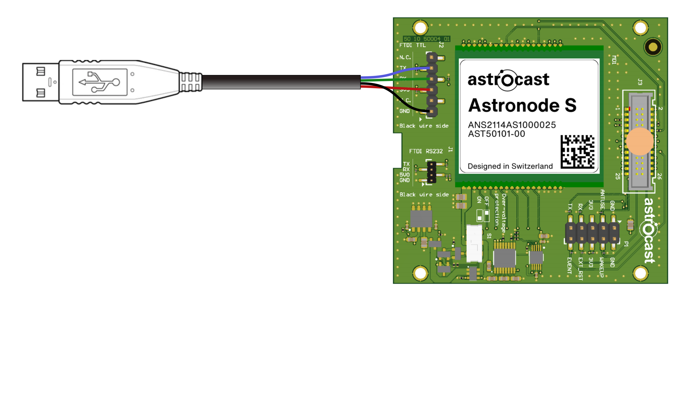
| UART | J2/J501 | FTDI cable compatible connector with 3.3V UART serial interface and 3.3V power line | Experimenting within a convenient distance to your computer using the supplied 1.8m UART cable |
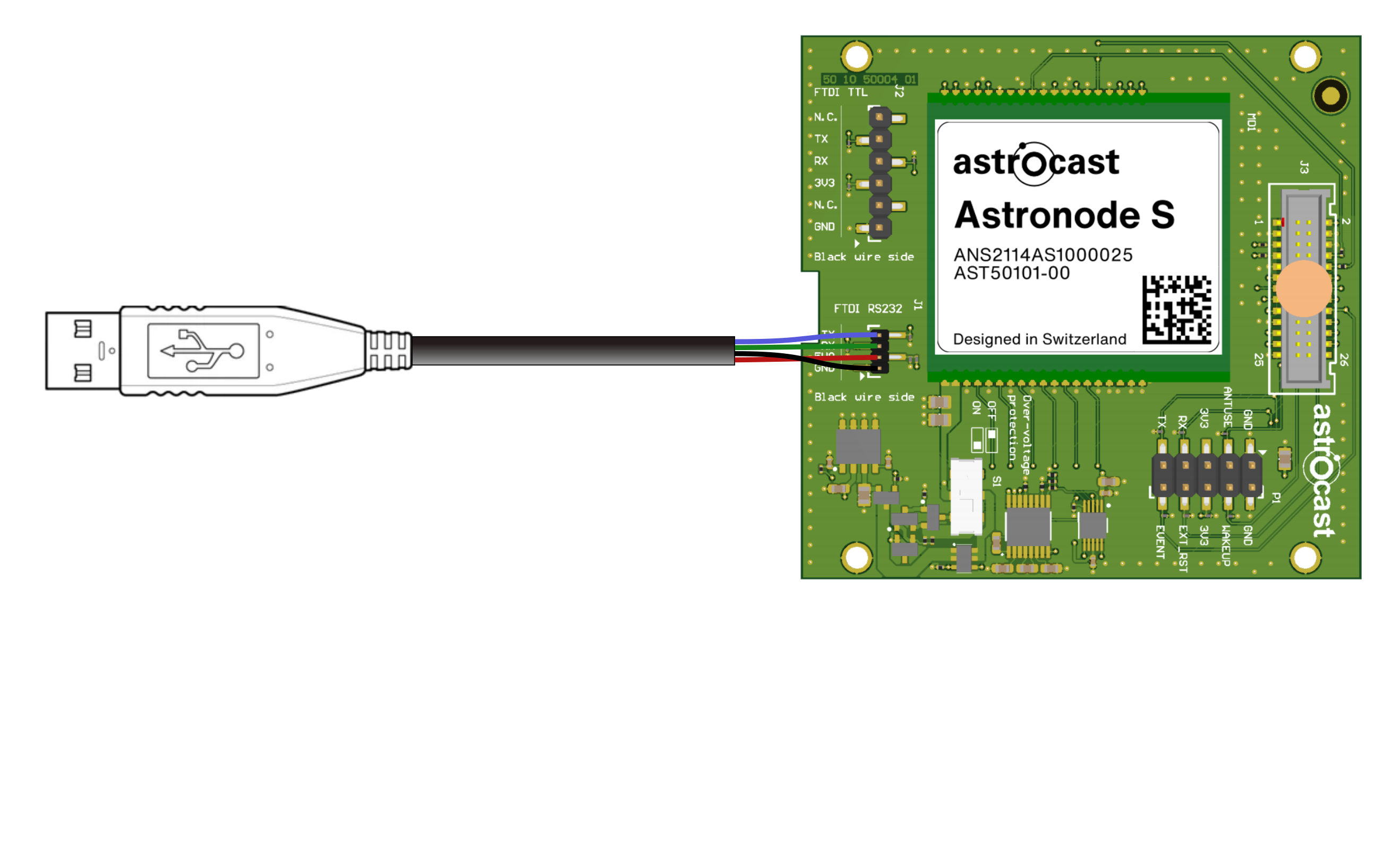
| RS232 | J1/J500 | FTDI cable compatible connector with 5.0V RS232 serial interface and 5.0V power line | Experimenting with a longer cable range from your computer, eventually having the Astronode Satellite Board outside with a view to the sky using the supplied 5m RS232 cable |
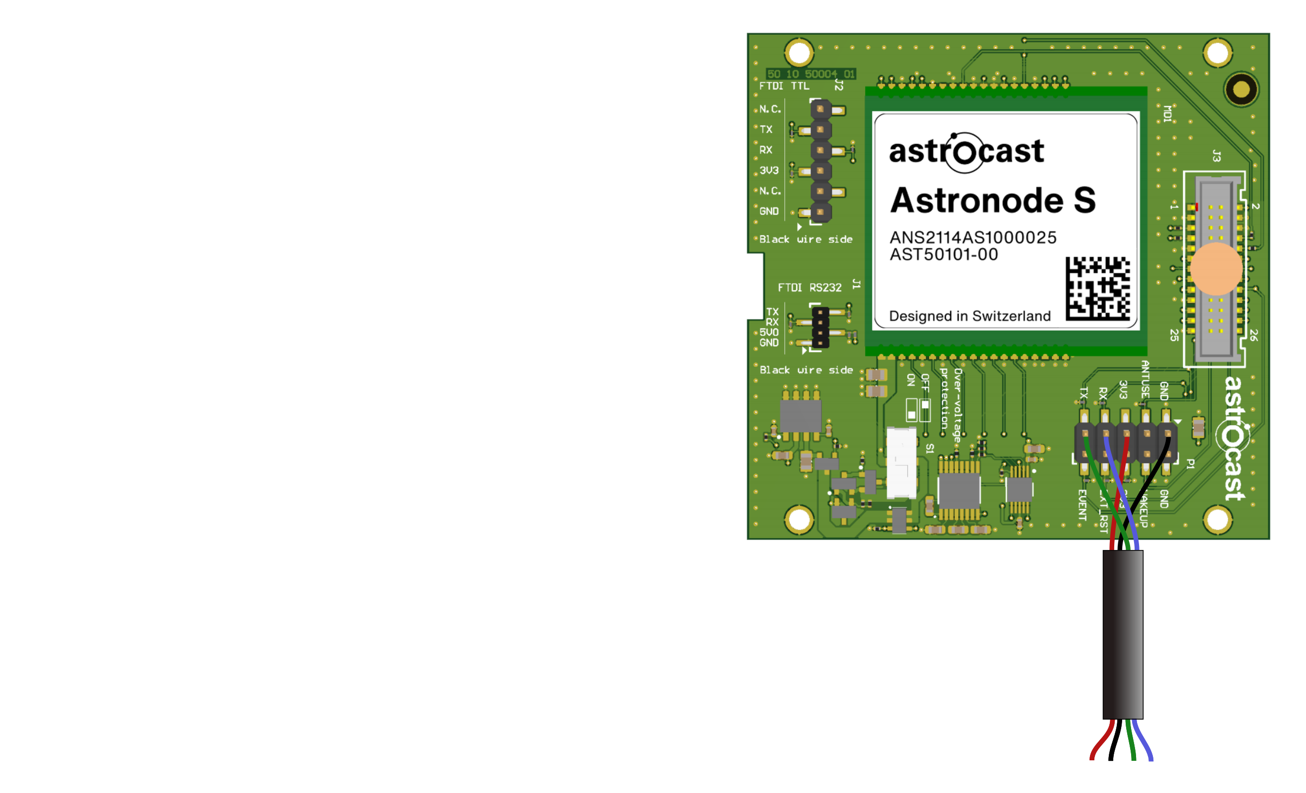
| Asset | P1/P400 | Full asset interface with power supply, Astronode S GPIO pins, and 3.3V UART serial interface | Connect the DevKit directly to your asset or test setup and experience the full low power and interrupt capabilities of the Astronode S |
UART interface

Board to cable 7-pin connector with a 2.54mm pitch. Compatible with the supplied 1.8m UART FTDI cable for connecting the DevKit to your computer. Use the FTDI virtual COM port on your computer for serial communication.
The FTDI cable provided has a higher power rating than standard FTDI cables available off the shelf. The Astronode Satellite Board will not work properly with other cables than the one provided by Astrocast
Use Case
Use this interface if you want to experiment within a convenient distance to your computer with both the DevKit boards. The connection is easy to set up on one of your computer's USB slots and will provide communication as well as 3.3V power supply to the DevKit.
For communication with the DevKit the following options are available:
- The Astronode GUI
- A serial console (like PuTTY)
- A Python Script
Connector identification
| Wi-FI board | Satellite board |
|---|---|
J501 | J2 |
Pin-out
| # | PIN | Description |
|---|---|---|
| 1 | N.C. | N/A |
| 2 | TX | DevKit data Tx line |
| 3 | RX | DevKit data Rx line |
| 4 | 3V3 | 3.3V |
| 5 | N.C. | N/A |
| 6 | GND | Ground |
RS232 interface

Board to cable 4-pin connector with a 1.27mm pitch. Compatible with the supplied 5m RS232 FTDI cable for connecting the DevKit to your computer. Use the FTDI virtual COM port on your computer for serial communication.
Use Case
Use this interface if you want to experiment within a longer distance to your computer with both the DevKit boards. The connection is easy to set up on one of your computer's USB slots and will provide communication as well as 5V power supply to the DevKit. The longer cable makes it possible to position the Astronode Satellite Board outside with view to the sky while having your computer inside a room.
You can't use the sleep mode low power capability of the Astronode S while using the RS232 interface. Not suitable for battery powered applications
For communication with the DevKit the following options are available:
- The Astronode GUI
- A serial console (like PuTTY)
- A Python Script
Connector identification
| Wi-FI board | Satellite board |
|---|---|
J500 | J1 |
Pin-out
| # | PIN | Description |
|---|---|---|
| 1 | TX | DevKit data Tx line |
| 2 | RX | DevKit data Rx line |
| 3 | 5V0 | 5V |
| 4 | GND | Ground |
Asset Interface

Board to cable 10-pin connector with a 2.54mm pitch. Use this connector to interface the DevKit with your own application with access to the complete Astronode S electrical interface.
Use Case
With access to the complete Astronode S electrical interface you can develop production firmware for your application before even integrating the Astronode S into your electronics. Use the Asset interface to connect the DevKit to the MCU and power supply of your own system.
Connector identification
| Wi-FI board | Satellite board |
|---|---|
P400 | P1 |
Pin-out
| # | PIN | Description |
|---|---|---|
| 1 | GND | Ground |
| 2 | ANT_USE | Antenna in use |
| 3 | 3V3 | 3.3V |
| 4 | RX | DevKit data Rx line |
| 5 | TX | DevKit data Tx line |
| 6 | GND | Ground |
| 7 | WAKEUP | Wake-up pin |
| 8 | 3V3 | 3.3V |
| 9 | EXT_RST | Reset |
| 10 | EVENT | Event notification |